Feature Posts

Showing posts with label DIY. Show all posts

RFI Shielding RTL-SDR with Blue Anodized Aluminum Enclosure


I currently own two NooElec RTL2832 + R820T2 SDR's that I use for spectrum scanning, and to trunk scan my local public safety radio calls that are always broadcasting (police, ambulance, fire, transit calls). I'll post more about that in a separate topic though.
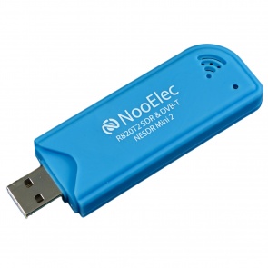


http://www.nooelec.com/store/sdr/nesdr-mini2-rtl2832u-r820t2.html

The RTL-SDR stands for Realtek-Software Defined Radio because it is based on the Realtek RTL2832U chipset. These are very cheap $20 devices that can be used as a computer based radio scanner. More can be read about them here: http://www.rtl-sdr.com/about-rtl-sdr/

These devices are however vulnerable to RF noises/interference, which can affect the noise floor and receiving capability of remote signals. The screenshot shown above was my SDR receiving signals in VHF, around the 130-140 MHz band. The noise floor was seen to be around -40dB.

A user named will1384 on reddit has put together a gallery of test results that he obtained after trying different methods of RFI shielding: 

Image gallery + his findings:

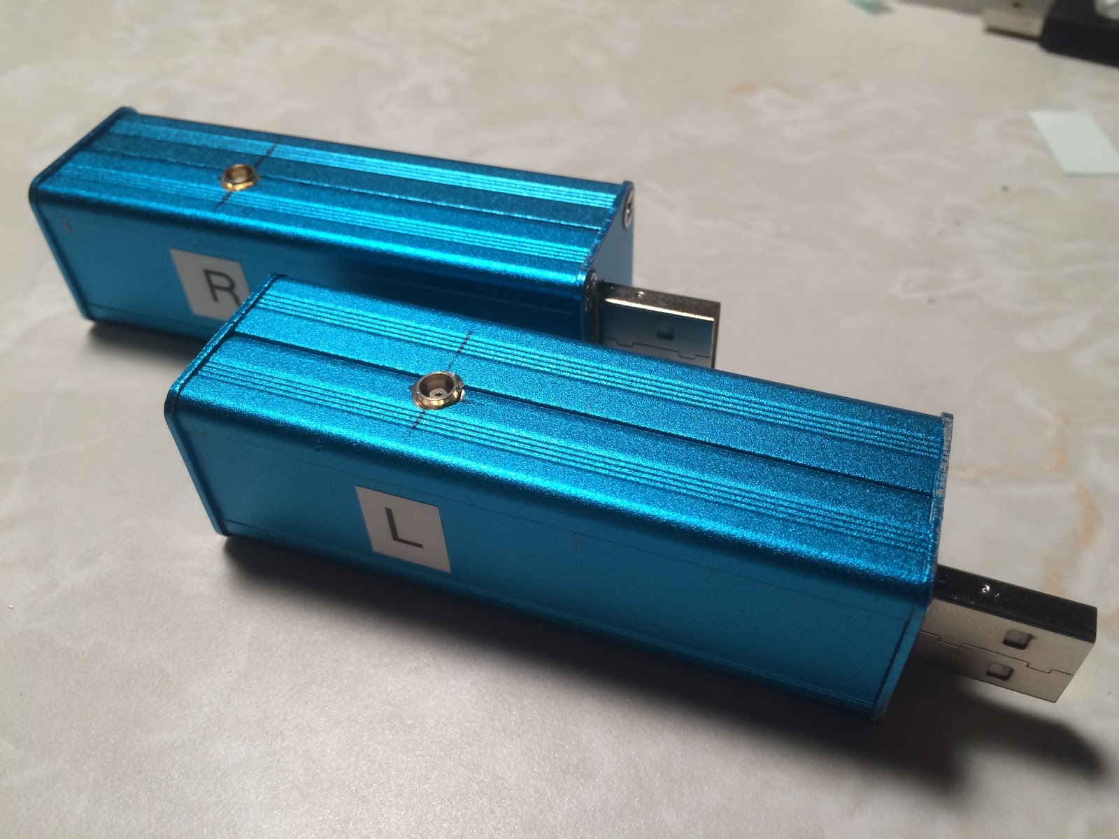
One of his methods was using a blue anodized aluminum enclosure like this one off eBay:

...so I bought two of these enclosures to see if it would have any effect. However, as he shows in his imgur gallery, I decided not to ground the USB PCB connection to the case like he did.

eBay aluminum enclosure and RTL-SDR casing taken off

Measured out where to drill a hole for the MCX connection on the SDR to fit

SDR was slid and snapped into place afterwards


One of the side plates needed to have a cutout for the USB to stick out


Final assembly

Times two

Hooked up to PC along with an antenna for each SDR


NooElec SDR in OEM plastic casing. Noise floor: around -40dB

NooElec SDR in blue aluminum enclosure. Noise floor: around -42.5dB


Although not too obvious, the noise floor did seem to drop by a few decibels. To improve my reception in the future, I plan to purchase a set of LNA's (low-noise amplifiers) to help pick up farther away radio signals.
Learn more »


iPhone 5s Rear Case Housing Swap (iPhone 6 Mini Mod)


I've been using an iPhone 5s for the past couple of years, and the internet has led me to a particular mod for it...so I bought this kit from eBay (black with black buttons) to try out. It has a nickname called the "iPhone 6 Mini" mod.

http://www.ebay.ca/itm/Rear-housing-for-iPhone-5-5s-back-battery-door-replacement-mod-to-iPhone-6-mini-/381178400878?var=&hash=item58c000d06e:m:m-uxI4Iq6HW4TEagox-PMWw

OEM iPhone 5s Rear Housing
eBay Rear Housing Kit for iPhone 5s
Installation:

Bottom: iPhone 5s with front screen removed, Top: Black iPhone 6 Mini empty housing
One hour later..internal components of iPhone 5s removed from the original housing (top)
Another hour later..internal components have been placed in the new black housing
Left: Finished iPhone 6 Mini, Right: iPhone 4s for size comparison
Left: iPhone 6 Mini, Right: iPhone 4s
More photos to show the curvature on the edges


Review: The quality of the case is decent, but the plastic/glass cover for the rear camera produced less sharp images when taking test photos. I believe that it may depend on the seller you buy from on eBay. Not all the mod kits are exactly the same, as I have seen ones that have a rear camera bezel that sticks out, similar to the new iPhone 6/6s feature. It also feels like the phone is lighter, perhaps by a few grams. The buttons work flawlessly, so I have no reason to switch back to the original 5s rear housing anytime soon. I'll be keeping it like this unless the case cracks some how..
Learn more »

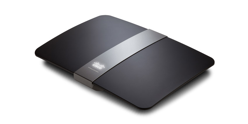
9dBi Antenna Modification on Linksys EA4500 Wireless Router


I have a Linksys EA4500 dual-band wireless N router that has 450 Mbps up and down speed in the 2.4GHz and 5GHz bands. I purchased it it back in 2012.


the newer AC routers coming out in 2016 as a replacement, I figured I would try a mod on this EA4500 model. On eBay there are these extremely long antennas that claim to have 9dBi of gain. They also come in smaller lengths and gain such as 7dBi, 6dBi, 3dBi.

eBay link: http://www.ebay.ca/itm/3-9dBi-RP-SMA-2-4-5-8GHz-WiFi-Antennas-3-U-fl-Cables-for-Mod-Kit-Asus-Router-/272060923777?

Here is the process that I went through:


The screws to disassemble the case are underneath these peg stands.

Disconnected all six of the 2.4/5GHz pigtail connectors.
The original antennas were removed and I drilled holes in these positions with a step drill.
SMA male connectors secured outside of the case with glue.
Antennas installed.
Final product.

My final verdict is that this modification did not benefit in any way. I was expecting possibly a small increase in RSSI % as some others have indicated with swapping to these chinese antennas. However I had the opposite result, and my RSSI dropped from 2-10% on both the 2.4 and 5GHz bands.
Learn more »

Building an affordable RepRap 3D Printer


I recently ordered a MakerFarm 8" Prusa i3 RepRap 3D Printer kit from http://www.makerfarm.com/.
Based off hours of research, I was able to narrow it down to this kit once I learned about the RepRap community. RepRap, short for replicating rapid prototyper, is an open source community for 3D printers involving hobbyists/DIYers, designers, engineers. The concept is that you can build your own printer for an affordable price, with back-end support for hardware and software from the community. There are many designs made available by various people, using the open design concept under the GNU General Public License. The particular design I liked was the Prusa i3, which is simple, yet very sturdy.

My initial research started with looking at consumer based ready to use printers off Kickstarter and other places like the MakerBot, Ultimaker, Pirate3D, Cube, and Printrbot. I dislike MakerBot a lot because of their claims about superb quality, overpriced hardware, and them starting to draw away from releasing open source designs. The only thing which is great is the Thingiverse repository for 3D models which they started since they were one of the earliest companies to produce a fully made 3D consumer printer.


Having a 3D printer will be very handy for quick production of enclosures, parts, and models designed throughout my engineering path.

Below are some more photos:
Assembling the printer

RAMPS 1.4 shield + Arduino MEGA 2560

Extruder mounted

Finished assembly with spool ready

Printing an object, with a new foam mat to reduce vibrations

3D printed fan nozzle with scoop to exhaust hot air from the hot end upwards (adjustable)

Light module using 4 LEDs in series with 100 ohm resistor

The module is running off of 12 V directly from the PSU

Learn more »

ATX Bench Power Supply Mod


Modifying a standard ATX power supply into a bench supply has become a popular thing to do, because it provides a selection of voltages to easily use. Standard power supplys will have +3.3V, +5V, +12V, and -12V.
I was able to buy this standard ATX psu for quite cheap, at around $14 on sale. The components and PCB are not the best quality, but it works, and has a low failure rate.
Following a few guides that are easily found online, I decided to modify this psu into my own bench supply, and here are the photos:


Luckily I had two DVD slot covers from my computer case that weren't needed, so I found that stacking them together made for a great face plate on the new bench supply. The blue LED (left side) is a status from the psu to signal that power is operating as normal when turned on. The flip switch with the safety cover (right side) is to control the on/off function. There is also another flip switch, which came built into the psu already (as most have), that controls the on/off. So in order to power up, this one must be set to on, and then the safety flip switch acts as the secondary control to make it actually turn on.

There's also a 12V to 5V DC USB module that I have, which could be put in to charge/power USB devices.

Learn more »